India's Largest Online Store. Best Prices . Discount Free Shipping · Easy Returns · Cash On Delivery

Showing posts with label Free Download & learn BE engineering final year project report. Show all posts

Thursday, 18 December 2014

Digital DC Voltmeter Using Microcontroller 8051(Atmel 89x52)

Digital DC voltmeter using Microcontroller or microprocessor is a project in which basically voltage of the system or circuit is measure and 7-segment or display on 16x2 Alpha numeric LCD(Liquid crystal display) This project is best suited for learning of voltage measurement and microcontroller or microprocessor based system from electronics or electrical field person or engineering or diploma student. In this project we are using digital measurement method in which we are uses ADC (Analog to digital convertor) to measure digital form of voltage and then processes this digital value using microprocessor or microcontroller 8051 from Atmel(89s52) then display this digital value on 7-segment or 16x2 Alpha numeric LCD. we can also use other microcontroller or microprocessor manufactures by NXP ARM, Microchip’s  PIC18f,PIC12F,PIC16F series…etc., STM series from STMicrotronics , freescale ,AVR etc. instated of Atmel 8051.Some of Microcontroller have inbuilt ADC Analog to digital converter .We are also provided or tested on computer simulation using simulation software Proteus.

Proteus Simulation-Digital DC voltmeter Using Microcontroller 8051(Atmel 89x52) www.beprojectidea.blospot.com
Proteus Simulation-Digital DC voltmeter Using Microcontroller 8051(Atmel 89x52)


Aim:

Design Digital voltmeter using microcontroller or microprocessor and display on 7-segment or 16x2 LCD(Liquid crystal display)we are using 7-segment in this simulation in Proteus.

Theory:


This introduction makes the link with analog voltage measurement.  The digital voltmeters  are simply compute digital values from ADC then processed and display on 7 segment.

A key element in processing digital signals is microcontroller. Microcontroller perform direct Manipulations signals. To completely describe digital voltmeter, three basic elements (or building blocks) are needed: an ADC(analog to digital converter 0808), a microcontroller, and a display device. The ADC 0808 has 10 inputs channels and 8-bit digital output


Software:


Keil uvision 3 3.30a

C51 8051 Compiler

Proteus 7.10 Labcenter Electronics

Component and Hardware:


          AT89S52 Microcontroller from Atmel
          ADC0808 Analog to Digital Converter 8-channel 8-bit Texas Instruments
          7-segment Multiples Display

C Code(C Programme):


//*******************************************************

//  *******  DC voltmeter ********           

//*******************************************************

//Company  : www.beprojectidea.blogspot.com

//Controller: 8051 Microcontroller ATMEL

// Compiler : C51 Keil uvision 3 3.30a

//Version     : 1.0

//*******************************************************


#include <AT89X52.H>


#define data_point P0    //data bus port

/* ADC0809 control pins */

sbit EOC  =P2^0;   

sbit ADDA =P2^1;                 

sbit ADDB =P2^2;

sbit ADDC =P2^3;

sbit OE   =P2^5;

sbit START=P2^6;

sbit CLK  =P2^7;

/* Global variables */

unsigned char disp[3]={0,0,0}; 

unsigned char t0count=0;       

/* Display function */

void display()

{

   unsigned char i,j,k=0x80;

   for(i=0;i<3;i++)        

     { 

                   P1=~0;             

              P3=disp[i];         

              P1=~k;               

                   k>>=1;             

              for(j=200;j>0;j--); 

     }

           P1=~0;

}

/*Function to Read ADC*/

unsigned char ADC0809()

{

  unsigned char d;

  ADDC=0;           

  ADDB=0;

  ADDA=0;

TR1=1;//enable timer

  START=1; START=0;  //start ADC

  while(EOC==0);     //check for EOC to go high


OE=1;              //enable output data

  d=data_point;      //read data

  OE=0;              //disable adc


  TR1=1;//stop timer

return d;          //return data

}

void covert(unsigned char x)

{

char code dispcode[]={0x3F,0x06,0x5B,0x4F,0x66,0x6D,0x7D,0x07,0x7F,0x6F};

  disp[0]=dispcode[x/50];

  disp[0]=disp[0]+0x80;  

  x=(x%50)*2;            

  disp[1]=dispcode[x/10]; //first decimal

  disp[2]=dispcode[x%10]; // second decimal

}

void main()

{

 TMOD=0X21;             //Enable timer 0 in mode 1 and timer 1 in momde 2

 TH0=(65536-10000)/256; //T0 for 10ms

 TL0=(65536-10000)%256;

 TH1=256-2;             // T1 for 2us

 ET0=1;

 ET1=1;

 EA=1;

 TR0=1;


 OE=0;      //Initilize ADC

 START=0;

 EOC=1;


 while(1)

 {

   display();   //display data

 }

}


void time0() interrupt 1

{

 TH0=(65536-10000)/256;

 TL0=(65536-10000)%256;

 t0count++;

 if (t0count==10)   //check for  1sec

 {

    t0count=0;

          covert(ADC0809()); //´convert data from adc

 }

}

void time1() interrupt 3

{

  CLK=~CLK;       //ADC clock pulse

}


CONCLUSION


We can measure voltage using digital voltmeter Using Microcontroller 8051(Atmel 89x52)  and compare with the analog voltmeter reading which almost accurate and we can further develop other meter in future such as ohmmeter, ammeter etc.we can also use other microcontroller or microprocessor manufactures by NXP ARM, Microchip’s  PIC18f,PIC12F,PIC16F series…etc., STM series from STMicrotronics , freescale ,AVR etc. instated of Atmel 8051.Some of Microcontroller have inbuilt ADC Analog to digital converter.


( Full Report)DOWNLOAD
(C Code and Computer Simulation) DOWNLOAD


Monday, 22 September 2014

ELECTRICAL(EEE) &ELECTRONIC(ECE) ENGINEERING REPORT (IEEE Format)AND PROJECT ON WIRELESS DATA TRANSFER USING PIC MICROCONTROLLER(pic18f4620) AND ZIGBEE(MRF24J40MA) 2.4Ghz


We are going to make WIRELESS DATA TRANSFER USING PIC(Peripheral Interface Controller) Microcontroller.The PIC18F4620 is a product of microchip. It is 8-bit controller and specially designed for ultra-low-power applications. A flexible clocking system multiple operating modes and Brown-Out Reset (BOR) are implemented to reduce power consumption and dramatically extend battery life. The data will be transmitted and received by using ZigBee transceiver module (MRF24J40MA).It is 2.4 GHz IEEE Std. 802.15.4™RF Transceiver Module .The input will be given from transmitter side by Three sets of switches and each set contains three push button switches .And the output(Graph) at the receiver side will be displayed on computer.

The results can be Analyses and processed by Visual Basic .NET software etc.
 This device can be applicable for the following applications:
  •  Reviewing public pole
  • EVM (Electronic Voting Machine)
  • Quiz contest.
System level diagram wireless data transfer pic18f4620 and mrf24j40ma zigbee engineering project report
 System level diagram wireless data transfer pic18f4620 and mrf24j40ma zigbee

Introduction

Aim:

The aim of the project is WIRELESS DATA TRANSFER USING PIC. It builds the wireless communication system, which will help transmitting data without any mesh of wires.

Introduction to topic:

We are going to built device for receiving wireless public pole. It is also useful for EVM (Electronic Voting Machine), Quiz contest etc. The input will be given from transmitter side from three sets of switches and each set contains three push button switches (A, B, C) to the slave PIC microcontroller. The microcontroller is serially communicated with the ZigBee transceiver module. The transmitted data is received at receiver side by ZigBee transceiver.  And the received data is given to master PIC by serial communication. The output will be displayed on computer.


Design Specification:

  • One master controller (PIC18F4620) and one slave controller (PIC18F4620)
  • Two ZIGBEE trans receiver module (MRF24J40MA)
  • 1 sets of switches, contents 4 switches
  • Computer for out put display.

Use of Software List:


  • MPLAB IDE V8.53 Compiler (Microchip Technology Inc)(free software for students from Micro Chip)
  • PicPgm –For programming PIC18f Hex file load into the Chip
  • Hyper Terminal Window XP Utility(Serial RS232 Interface)
  • Eagle layout Editor 6.0.1(if we want to designe PCB(Printed Circuit Board))
  • Proteus 7 Professional for Simulation and testing

Use of Hardeware List:


  • PIC18F4620 Microcontroller IC (Microchip Technology Inc) – 2 Pisces
  • MRF24J40MA  ZigBee transceiver Modual (Microchip Technology Inc)– 2 Pisces
  • General purpose PCB (GPP)
  • Soldering iron,solder wire,Connector,Power Supply (SMPS ) 5Volt 2A etc.
  • Push button switches
 

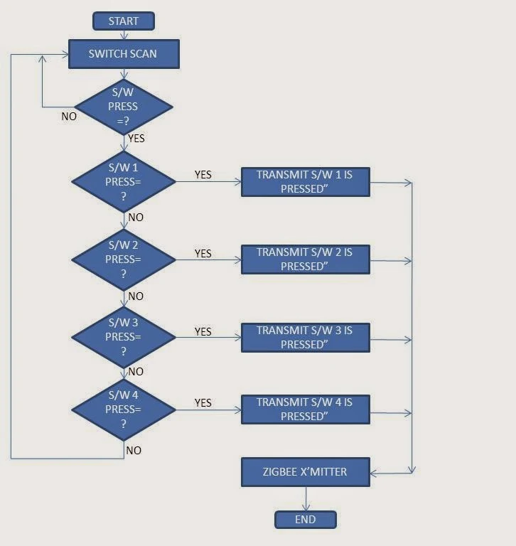
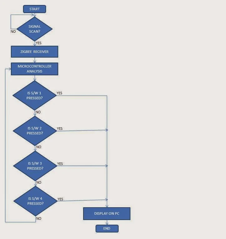
  • Flow Chart:

Transmitter:


Flowchart of Transmitter wireless data transfer pic18f4620 and mrf24j40ma zigbee engineering project report
Flowchart of Transmitter wireless data transfer pic18f4620 and mrf24j40ma zigbee

           Receiver:


Flowchart of Receiver wireless data transfer pic18f4620 and mrf24j40ma zigbee engineering project report
Flowchart of Receiver wireless data transfer pic18f4620 and mrf24j40ma zigbee

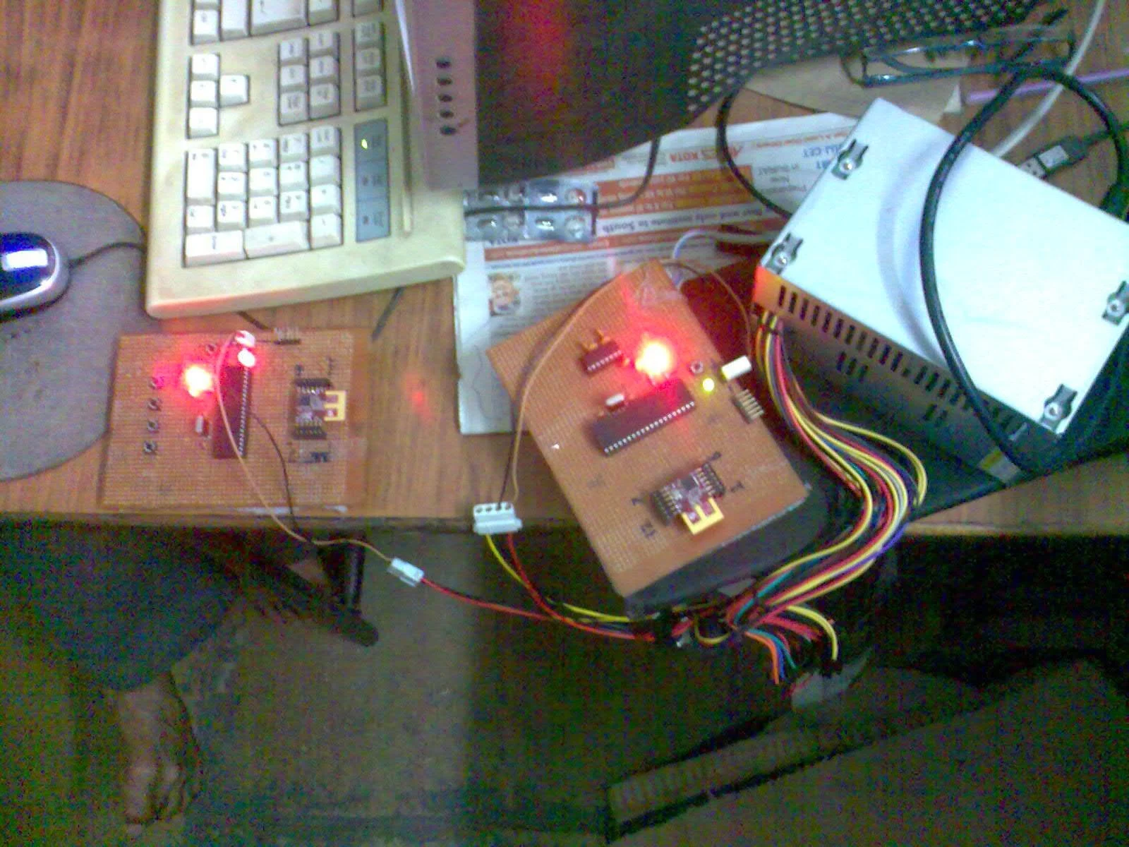
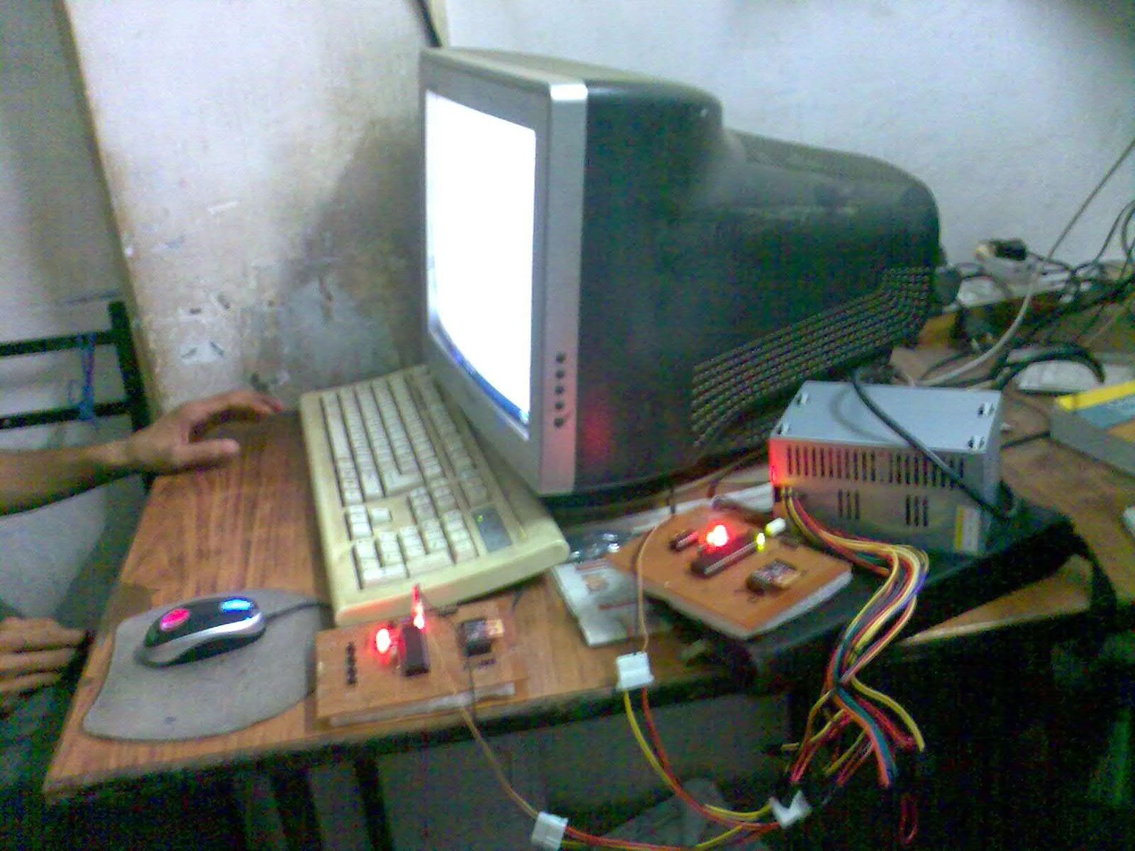
  • Hardware Implementation and PCB Connection:

Hardware Implementation and PCB Connection wireless data transfer pic18f4620 and mrf24j40ma zigbeeHardware Implementation and PCB Connection wireless data transfer pic18f4620 and mrf24j40ma zigbee
  • Observation 

 The out put of receiver is shown on computer using Hyper Terminal. The out put snap shots are        shown below:
1. Zigbee co-coordinator initialized and turning on joining with End device.
2.After pressing key 1 and it is displayed on hyper terminal.
3. After pressing key 2 and it is displayed on hyper terminal. 
4. After pressing key 3 and it is displayed on hyper terminal.
5. After pressing key 4 and it is displayed on hyper terminal.


Observation hyper terminal snapshot wireless data transfer pic18f4620 and mrf24j40ma zigbee

Observation hyper terminal snapshot wireless data transfer pic18f4620 and mrf24j40ma zigbee

Observation hyper terminal snapshot wireless data transfer pic18f4620 and mrf24j40ma zigbee

Suggestion For Further Advancement

  • Here it is only a one Transmitter module but as per requirements it is compatible with more than one transmitter module.
  •  If LCD display is placed on each transmitter and receiver module. The transmitted question will be displayed on each student’s module and the answer will be displayed on Examiner’s module. It is possible because ZigBee is a trans receiver module.

Application Area Of Project

  •  Reviewing Public Pole
  •  EVM [Electronic Voting Machine]
  •  Quiz Contest

Conclusion

In today’s world use of Wireless Data Transfer becomes primary demand for the industrial application. The efficient transmitter and receiver unit with high processing capabilities for both the modules which can process the received information give optimization result has become necessity.
Keeping these things in mind we have come up with an idea to transmit and receive data wireless using ZigBee and PIC controller which mostly suffices the above requirement. The result has been shown and verified.

Bibliography and References


[1]Muhammad Ali Mazidi,Janice Gillispie Mazidi,Rolin D. McKinlay, The Microcontroller and Embedded Systems,2nd Edition,Prentice Hall (page no.24)

[2] http://www.microchip.com/wwwproducts/Devices.aspx?dDocName=en535967

[3] http://ww1.microchip.com/downloads/en/DeviceDoc/39626e.pdf

[4] http://www.media.digikey.com/.../MRF24J40MA-I%5ERM.JPG

[5] http://www.microchip.com/wwwproducts/Devices.aspx?dDocName=en535967

[6] http://ww1.microchip.com/downloads/en/DeviceDoc/39626e.pdf

[7] http://www.microchip.com/wwwproducts/Devices.aspx?dDocName=en535967

[8] http://www.microchip.com/wwwproducts/Devices.aspx?dDocName=en535967

[9]http://ieeexplore.ieee.org/stamp/stamp.jsp?tp=&arnumber=1559520&isnumber=33126

[10] Ajay V Deshmukh, Microcontrollers Theory and Application, Tata McGraw- Hill
        Publishing   Company Limited

[11] Richard Barnett, Larry O’cull, Embedded C Programming and the Microchip PIC.

[12] Chien C.-N., Hsu, H.-W., Jang J.-K., Rau C.-L., and Jaw F.-S., “Microcontroller-based wireless recorder for biomedical signals,” Proceedings of the 2005 IEEE Engineering in Medicine and Biology 27th Annual Conference Shanghai, China, September 1-4, 2005.

[13]  www.datasheetcatalog.org/datasheet/texasinstruments/max232.pdf

[14] Geer, D., “Users Make a Beeline for ZigBee Sensor Technology,” IEEE Computer Society,  Vol. 38, pp 16-19, December 2005.